SP3491

3.3V Low Power Full Duplex RS-485 Transceivers with 10Mbps Data Rate
Order Now

Overview

Information 3.3V Low Power Full Duplex RS-485 Transceivers with 10Mbps Data Rate
Supported Protocols RS-422, RS-485
Supply Voltage (Nom) (V) 3.3
No. of Tx 1
No. of Rx 1
Duplex Full
Data Rate (MAX) (Mbps) 10
HBM ESD (kV) 2
IEC 61000-4-2 Contact (±kV) -
Rx Fail-Safe Standard
Multi-Drop Nodes 32
Transient Tolerance (V)
Fault Tolerance (V)
VL Pin
Temperature Range (°C) 0 to 70, -40 to 85
Package NSOIC-14
ICC (Max) (mA) 2
Shutdown
Typ Shutdown Current (µA) 10
Hot Swap
PROFIBUS (5V) or High Output (3V)
Show more

The SP3490 and SP3491 devices are +3.3V low power full-duplex transceivers that meet the specifications of the RS-485 and RS-422 serial protocols. These devices are pin-to-pin compatible with the MaxLinear SP490 and SP491 devices as well as popular industry standards. The SP3490 and SP3491 feature MaxLinear's BiCMOS process, allowing low power operation without sacrificing performance. The SP3490 and SP3491 meet the electrical specifications of the RS-485 and RS-422 serial protocols up to 10Mbps under load. The SP3491 is identical to the SP3490 with the addition of driver and receiver tri-state enable lines.

  • Full Duplex RS-485 and RS-422 Transceivers
  • Operates from a single +3.3V supply
  • Interoperable with +5.0V logic
  • Driver/Receiver Tri-state Enable Lines
  • -7V to +12V Common-Mode Input Voltage Range
  • +200mV Receiver Input Sensitivity
  • Allows up to 32 transceivers on the serial bus
  • Compatibility with LTC491 and SN75180

Documentation & Design Tools

Type Title Version Date File Size
Data Sheets SP3490/SP3491 +3.3V Low Power Full-Duplex RS-485 Transceivers with 10Mbps Data Rate 1.0.3 September 2017 481.9 KB
Application Notes AN-291, RS-485 Advanced Fail-Safe Feature R01 May 2023 3.7 MB
Application Notes RS-232 and RS-485 PCB Layout Application Note R00 December 2022 2.8 MB
Application Notes AN-292, RS-485 Cable Lengths vs Data Signaling Rate R01 July 2022 2.7 MB
Application Notes ANI-13, RS-485 and RS-422 Physical Topologies D December 2006 183.2 KB
Product Brochures Interface Brochure November 2023 3.7 MB
Product FAQs SP3491 FAQ 1.0.0 October 2006 179.8 KB
Register for a myMxL account or Login to myMxL to view all Technical Documentation & Design Tools.

Quality & RoHS

Part Number RoHS | Exempt RoHS Halogen Free REACH TSCA MSL Rating / Peak Reflow Package
SP3491CN-L N Y Y Y Y L2 / 260ᵒC NSOIC14
SP3491CN-L/TR N Y Y Y Y L2 / 260ᵒC NSOIC14
SP3491EN-L N Y Y Y Y L2 / 260ᵒC NSOIC14
SP3491EN-L/TR N Y Y Y Y L2 / 260ᵒC NSOIC14

Click on the links above to download the Certificate of Non-Use of Hazardous Substances.
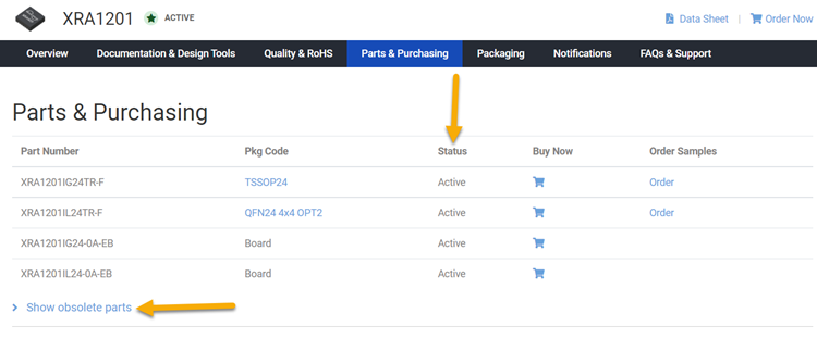
Additional Quality Documentation may be available, please Contact Support.

Parts & Purchasing

Part Number Pkg Code Min Temp Max Temp Status Suggested Replacement Buy Now Order Samples PDN
SP3491CN NSOIC14 0 70 OBS SP3491CN-L
SP3491CN-L NSOIC14 0 70 Active Order
SP3491CN-L/TR NSOIC14 0 70 Active Order
SP3491CN/TR NSOIC14 0 70 OBS SP3491CN-L/TR
SP3491EN NSOIC14 -40 85 OBS SP3491EN-L
SP3491EN-L NSOIC14 -40 85 Active Order
SP3491EN-L/TR NSOIC14 -40 85 Active Order
Show obsolete parts
Part Status Legend
Active - the part is released for sale, standard product.
EOL (End of Life) - the part is no longer being manufactured, there may or may not be inventory still in stock.
CF (Contact Factory) - the part is still active but customers should check with the factory for availability. Longer lead-times may apply.
PRE (Pre-introduction) - the part has not been introduced or the part number is an early version available for sample only.
OBS (Obsolete) - the part is no longer being manufactured and may not be ordered.
NRND (Not Recommended for New Designs) - the part is not recommended for new designs.

Packaging

Pkg Code Details Quantities Dimensions PDF
NSOIC14
  • JEDEC Reference: MS-012
  • MSL Pb-Free: L2 @ 260ºC
  • MSL SnPb Eutectic: n/a
  • ThetaJA: 88.2ºC/W
  • Bulk Pack Style: Tube
  • Quantity per Bulk Pack: 56
  • Quantity per Reel: 2500
  • Quantity per Tube: 56
  • Quantity per Tray: n/a
  • Reel Size (Dia. x Width x Pitch): 330 x 16 x 8
  • Tape & Reel Unit Orientation: Quadrant 1
  • Dimensions: mm
  • Length: 8.65
  • Width: 3.90
  • Thickness: 1.75
  • Lead Pitch: 1.27

Notifications

Distribution Date Description File
12/19/2016 Qualification of alternate assembly subcon, ANST, China.
08/12/2016 Addition of an alternate qualified location, JCET, for assembly using copper wire bonding.
02/11/2016 Foundry line qualification, Addition of qualified 6 inch wafer processing line in Silan
09/11/2015 Alternate assembly site Addition of an alternate assembly supplier Greatek in Taiwan.
10/03/2013 Qualification of SiO2 5KÅ + SiN 7KÅ passivation to replace PSG 10KÅ passivation. Material & Process Changes.
07/02/2013 Addition of an alternate qualified assembly supplier, Carsem (Malaysia) for 14 and 16 lead NSOIC package using copper wire bonding. Material change.
02/02/2012 Design Change: Poly layer changed to optimize the receiver gate length. To improve device performance and production consistency.
07/30/2010 Process Change. Capacity enhancement.
12/07/2009 Enhancement of NSOIC 8, NSOIC14 and NSOIC16 packages to Green (halogen-free) via Mold Compound & Die Attach Material. Enhance packages to be Green (halogen-free).
05/19/2009 Notice of Obsolescence Discontinued by Exar Corporation due to low market demand
11/26/2008 Notice of Obsolescence Package Discontinuation Notice
02/28/2007 Product Obsolescence Letter and Discontinuation Notification. Discontinued.
02/02/2006 Announcing transfer of certain Power Management and Interface Products from Hillview fabrication facility to wafer foundary Episil. See attached Product List Power Management and Interface products as listed are being transfer to external wafer foundry, due to cessation of operations of the sipex Hillview Fabrication manufacturing site

FAQs & Support

Search our list of FAQs for answers to common technical questions.
For material content, environmental, quality and reliability questions review the Quality tab or visit our Quality page.
For ordering information and general customer service visit our Contact Us page.

Submit a Technical Support Question As a New Question

For RS-232 it is 50 feet (15 meters), or the cable length equal to a capacitance of 2500 pF, at a maximum transmission rate of 19.2kbps. When we reduce the baud rate, it allows for longer cable length. For Example:


Baud Rate (bps)

Maximum RS-232 Cable Length (ft)

19200

50

9600

500

4800

1000

2400

3000

 
For RS-485 / RS-422 the data rate can exceed 10Mbps depending on the cable length. A cable length of 15 meters (50 feet) will do a maximum of 10Mbps. A cable length of 1200 meters (4000 feet) will do a maximum of 90kbps over 24 AWG gauge twisted pair cable (with 10 pF/ft). Refer to Annex A TIA/EIA-422-B. Also refer the RS-485 Cable Lengths vs. Data Signaling Rate Application Note (AN-292).


As RS-422/RS-485 uses differential signaling, it is more immune to noise and longer cables and/or high data rates can be used, especially in noisy environments. Also, RS-485 allows for multi-point operation, up to 32 unit loads. Transceivers may use a fraction of a unit load, increasing the number of devices on the bus. For example, the XR33152 receiver input impedance is at least 120 k, which equates to 1/10 of a unit load. Therefore, XR33152 allows more than 320 devices (32 x 10) on the bus.

Fail Safe is an attempt to keep the output of the RS-485 receiver to a known state. Transceivers may have standard fail safe or advanced / enhanced receiver fail safe features. Standard fail safe supports open inputs while enhanced fail safe transceivers such as the SP339 and XR34350 support open input, shorted input and undriven terminated lines without external biasing. See Application Note ANI-22 for more detail.


Figure 1:  Standard Failsafe Receiver Sensitivity Range


Figure 2: Standard Failsafe with Open Input


Figure 3: Enhanced Failsafe Receiver Sensitivity Range


Figure 4:  Enhanced Failsafe with Open Input


Figure 5:  Enhanced Failsafe with Shorted Input


Figure 6:  Enhanced Failsafe with Un-driven terminated lines


Yes, this is possible using one RS-485 transceiver. The microcontrollers will have to be addressable and have tri-state outputs. The RS-485 device can be controlled by the host via the DE/RE pin. The micros will have to be in either receiving mode or tri-state mode when the RS-485 transceiver is transmitting data. When the host transmits it will have to send an address to the specific micro. If any micro transmits the transceiver will have to be in receiving mode and all other micros will have to be in receive or tri-state. So the host would have to initiate this sequence by addressing the micro first then switch the transceiver to receive.
The half duplex system would have a bus with one transceiver and multiple microcontrollers all tied to the bus. For 5V systems the SP485 family can be used. For 3V systems the SP3070 family can be used. The require speed will determine the part number. The SP3078 part runs up to speeds of 16Mbps.  See the parametric search on https://www.exar.com/products/interface/serial-transceivers/rs485-422 for more options.
Care must be taken to assure the transceiver can drive the multiple micros in RX mode.

ESD tests are “destructive tests.” The part is tested until it suffers damage. Therefore parts cannot be 100% tested in production, instead a sample of parts are characterized during the product qualification. The test procedure consists of “zapping” pins with a given voltage using the appropriate model and then running the part through electrical tests to check for functionality or performance degradation.

ESD is caused by static electricity. In order for an ESD event to occur there must be a buildup of static charge. Very high charge levels are actually quite rare. In a normal factory environment, taking basic ESD precautions (grounding-straps, anti-static smocks, ionizers, humidity control, etc.) static levels can be kept below a few tens of volts. In an uncontrolled environment, like an office, static levels rarely get above 2000 volts. Under some worstcase conditions (wearing synthetic fabrics, rubbing against synthetic upholstered furniture, extremely low humidity)
levels can go as high as 12 to 15 thousand volts. Actually to get to 15000 volts or higher you would need to be in an uncomfortably dry environment (humidity below 10%) otherwise static charge will naturally dissipate through corona discharge. It would definitely be considered a “bad hair day.” Humans can generally feel a static shock only above 3000 volts. A discharge greater than 4000 volts can cause an audible “pop.” But repeated lower level discharges can be imperceptible and still may have a cumulative damaging effect on sensitive ICs. All ICs, even those with robust protection, can be damaged if they are hit hard enough or often enough.

Most ICs in a typical system are at greatest risk of ESD damage in the factory when the PCB is assembled and the system is being built. After the system is put together they are soldered onto the PCB and shielded within a metal or plastic system enclosure. Interface ICs are designed to attach to an external connector that could be exposed to ESD when a cable is plugged in or when a person or object touches the connector. These interface pins are most likely to see ESD exposure and therefore benefit from additional protection.

Actually the letter “E” could have two different meanings, depending on where it is in the part number. Most of our interface devices are available in different temperature grades. Commercial temperature (0 to 70C) has a “C” after the numeric part number. Industrial-extended temperature (-40 to +85C) use the letter E. So for example SP485CN is commercial and SP485EN is industrial. The second letter indicates the package type, in this case N for narrow-SOIC. Another E in the suffix indicates that this device has enhanced ESD protection, typically of ±15000Volts on the interface pins. Devices that do not have the enhanced ESD still contain built-in ESD protection of at least ±2000Volts. For example the SP485ECN is ESD rated up to ±15kV, and the SP485CN is rated for ±2kV HBM.

Visit the product page for the part you are interested in.  The part's status is listed in the Parts & Purchasing section.  You can also view Product Lifecycle and Obsolescence Information including PDNs (Product Discontinuation Notifications).
 
To visit a product page, type the part into the search window on the top of the MaxLinear website.
 
In this example, we searched for XRA1201.  Visit the product page by clicking the part number or visit the orderable parts list by clicking "Orderable Parts". 


The Parts & Purchasing section of the product page shows the Status of all orderable part numbers for that product.  Click Show obsolete parts, to see all EOL or OBS products.


Videos

Tips to Maintain a Successful RS-485 Link

This video provides four tips to help maintain RS-485 serial communication without data loss