Overview
| Information | Hi-Speed USB to 10/100 Ethernet Bridge w/1-CH UART |
|---|---|
| CPU Interface | USB 2.0 |
| Ethernet MAC/PHY (Mbps) | 10/100 |
| UART CH | 1 |
| Max Data Rate (Mbps) | 15 |
| UART Tx/Rx FIFO (Bytes) | 1024/1024 |
| Auto Half-Duplex Control | ✔ |
| No. of GPIOs | 8 |
| I2C Master | ✔ |
| HBM ESD (USB) (kV) | ±15kV HBM |
| Supply Voltage Range VCC (V) | 4.4 to 5.25 |
| Max UART/GPIO Input Voltage (V) | 3.6 |
| Max UART/GPIO Output Voltage (V) | 3.6 |
| Temperature Range (°C) | -40 to 85 |
| Package | QFN-32 |
The XR22801 is a Hi-Speed USB 2.0 compound device with an embedded hub and 4 downstream USB functions: 10/100 Ethernet MAC and PHY, UART, multi-master capable I2C controller, and an Enhanced DedicatedGPIO Entity (EDGE) controller.
The upstream USB interface has an integrated USB 2.0 PHY and device controller that is compliant with both Hi-Speed (480Mbps) and Full-Speed (12Mbps) USB 2.0. The vendor ID, product ID, power mode, remotewakeup support and maximum power consumption are amongst the values that can be programmed using the on-chip One-Time Programmable (OTP) memory.
The Ethernet 10/100 MAC and PHY are compliant with IEEE 802.3 and supports auto-negotiation, auto-MDIX, checksum offload, auto-polarity correction in 10Base-T and remote wakeup capabilities.
The enhanced UART has a maximum data rate of 15 Mbps. Using a fractional baud rate generator, any baud rate between 300 bps and 15 Mbps can be accurately generated. In addition, the UART has a large 1024-byte TX FIFO and RX FIFO to optimize the overall data throughput for various applications. The automatic RS485 control feature simplifies both the hardware and software for half-duplex RS-485 applications. If required, the multidrop (9-bit) mode feature further simplifies typical multidrop applications by enabling / disabling the UART receiver depending on the address byte received.
The multi-master capable I2C controller and EDGE controller (up to 16 GPIOs) can be accessed via the USB HID interface. The EDGE pins or I2C interface can be used for controlling and monitoring other peripherals. Up to 2 EDGE pins can be configured as a PWM generator.
- USB 2.0 Compliant Interface
- 10/100 Ethernet MAC and PHY
- Enhanced UART
- Half-Duplex Mode
- I2C Multi-master
- Enhanced Dedicated GPIO Entity (EDGE)
- Single +5.0V Power Supply Input
- Regulated +3.3V Output Power
- Single 25MHz Crystal
- ±15kV HBM ESD Protection on USB data pins
- ±8kV HBM ESD Protection on all other pins
- USB to Ethernet Dongles
- POS Terminals
- Test Instrumentation
- Networking
- Factory Automation and Process Controls
- Industrial Applications
Documentation & Design Tools
| Type | Title | Version | Date | File Size |
|---|---|---|---|---|
| Data Sheets | XR22801 Hi-Speed USB to 10/100 Ethernet Bridge | 1D | April 2019 | 993.4 KB |
| Application Notes | AN202, USB UART Board Design Considerations for USB Compliance | R02 | June 2023 | 2.4 MB |
| Application Notes | AN-226, Windows Driver Customization for USB UARTs | R00 | February 2020 | 2.5 MB |
| User Guides & Manuals | XR2280x USB Ethernet Bridges Design Guide | 00 | April 2020 | 2.3 MB |
| User Guides & Manuals | XR22801 Evaluation Board User’s Manual | 1A | June 2014 | 1.4 MB |
| Software: GUIs & Utilities | Sample USB UART GUI (Serial Test App) | 1.2.0.0 | July 2021 | 1.4 MB |
| Software: GUIs & Utilities | Android Application | 1C | November 2015 | 476.6 KB |
| Errata | XR2280x Errata | R01 | July 2022 | 2.3 MB |
| Product Flyers | Full-Speed USB UART Family | 1.1 | November 2020 | 605.3 KB |
| Schematics & Design Files | XR22801 Evaluation Board BRD, RSN Files | June 2016 | 331.6 KB | |
| Schematics & Design Files | Evaluation Board Schematic | 2.0 | February 2016 | 35.9 KB |
| Software: Drivers | Linux 3.6.x and Newer | 1G | August 2024 | 29.7 KB |
| Software: Drivers | Windows 10 and newer | 2.7.0.0 | January 2023 | 169.2 KB |
| Software: Drivers | Windows 11 | 1.1.0.2 | January 2023 | 42.5 KB |
| Software: Drivers | Windows 7, 8 | 2.6.0.0 | December 2019 | 145.7 KB |
| Software: Drivers | Windows 10 | 1.1.0.1 | June 2018 | 78 KB |
| Software: Drivers | Windows XP, Vista, 7 | 1.1.0.0 | December 2017 | 86 KB |
| Software: Drivers | XRUSB1 for Win XP SP3 and newer | 2.2.5.0 | March 2016 | 1 MB |
| Software: Drivers | Linux 2.6.18 to 3.4.x | 1A | January 2015 | 19.1 KB |
| Product Brochures | Serial Transceivers & Bridges Brochure | R03 | May 2025 | 3.6 MB |
Quality & RoHS
| Part Number | RoHS | Exempt | RoHS | Halogen Free | REACH | TSCA | MSL Rating / Peak Reflow | Package |
|---|---|---|---|---|---|---|---|
| XR22801IL32TR-F | N | Y | Y | Y | Y | L2 / 260ᵒC | QFN32 5x5 OPT3 |
Click on the links above to download the Certificate of Non-Use of Hazardous Substances.
Parts & Purchasing
| Part Number | Pkg Code | Min Temp | Max Temp | Status | Suggested Replacement | Buy Now | Order Samples | PDN |
|---|---|---|---|---|---|---|---|---|
| XR22801IL32-F | QFN32 5x5 OPT3 | -40 | 85 | OBS | XR22801IL32TR-F | |||
| XR22801IL32TR-F | QFN32 5x5 OPT3 | -40 | 85 | Active | Order | |||
| XR22801IL32-0A-EB | Board | Active |
Active - the part is released for sale, standard product.
EOL (End of Life) - the part is no longer being manufactured, there may or may not be inventory still in stock.
CF (Contact Factory) - the part is still active but customers should check with the factory for availability. Longer lead-times may apply.
PRE (Pre-introduction) - the part has not been introduced or the part number is an early version available for sample only.
OBS (Obsolete) - the part is no longer being manufactured and may not be ordered.
NRND (Not Recommended for New Designs) - the part is not recommended for new designs.
Packaging
| Pkg Code | Details | Quantities | Dimensions |
|---|---|---|---|
| QFN32 5x5 OPT3 |
|
|
|
Notifications
FAQs & Support
Search our list of FAQs for answers to common technical questions.
For material content, environmental, quality and reliability questions review the Quality tab or visit our Quality page.
For ordering information and general customer service visit our Contact Us page.
Submit a Technical Support Question As a New Question
For some UARTs, Microsoft certified drivers are available for Windows Operating System and can be downloaded via Windows Update. These drivers and others, including for Linux and other Operating Systems can be found by visiting https://www.exar.com/design-tools/software-drivers Please note Software Driver Use Terms.


Click on the version link under Driver Version of the desired type of UART, part number and operating system. A zip file is downloaded which contains a ReadMe file with instructions.
Links to datasheets and product family pages are in the software driver table for easy reference.Find the product page of the part that you want to get an evaluation board for and click on Parts & Purchasing. Example:

Click on Parts & Purchasing or Order Now. Locate the icons under Buy Now or Order Samples:

Click on the Buy Now icon and see who has stock and click on the Buy button:

Alternatively, you can click on the Order Samples icon to request a sample.
Note, not all products are sampleable from the website.

If the icons are missing, create a support ticket.
ESD tests are “destructive tests.” The part is tested until it suffers damage. Therefore parts cannot be 100% tested in production, instead a sample of parts are characterized during the product qualification. The test procedure consists of “zapping” pins with a given voltage using the appropriate model and then running the part through electrical tests to check for functionality or performance degradation.
ESD is caused by static electricity. In order for an ESD event to occur there must be a buildup of static charge. Very high charge levels are actually quite rare. In a normal factory environment, taking basic ESD precautions (grounding-straps, anti-static smocks, ionizers, humidity control, etc.) static levels can be kept below a few tens of volts. In an uncontrolled environment, like an office, static levels rarely get above 2000 volts. Under some worstcase conditions (wearing synthetic fabrics, rubbing against synthetic upholstered furniture, extremely low humidity)
levels can go as high as 12 to 15 thousand volts. Actually to get to 15000 volts or higher you would need to be in an uncomfortably dry environment (humidity below 10%) otherwise static charge will naturally dissipate through corona discharge. It would definitely be considered a “bad hair day.” Humans can generally feel a static shock only above 3000 volts. A discharge greater than 4000 volts can cause an audible “pop.” But repeated lower level discharges can be imperceptible and still may have a cumulative damaging effect on sensitive ICs. All ICs, even those with robust protection, can be damaged if they are hit hard enough or often enough.
Most ICs in a typical system are at greatest risk of ESD damage in the factory when the PCB is assembled and the system is being built. After the system is put together they are soldered onto the PCB and shielded within a metal or plastic system enclosure. Interface ICs are designed to attach to an external connector that could be exposed to ESD when a cable is plugged in or when a person or object touches the connector. These interface pins are most likely to see ESD exposure and therefore benefit from additional protection.
https://www.exar.com/quality-assurance-and-reliability/lead-free-program
Visit the product page for the part you are interested in. The part's status is listed in the Parts & Purchasing section. You can also view Product Lifecycle and Obsolescence Information including PDNs (Product Discontinuation Notifications).
To visit a product page, type the part into the search window on the top of the MaxLinear website.
In this example, we searched for XR33180. Visit the product page by clicking the part number or visit the orderable parts list by clicking "Orderable Parts".

The Parts & Purchasing section of the product page shows the Status of all orderable part numbers for that product. Click Show obsolete parts, to see all EOL or OBS products.

USB peripheral devices may operate in bus or self-powered modes. In bus powered mode, the peripheral device is powered by the USB host 5V VBUS power either directly, or for example through a voltage regulator that might provide a regulated 3.3V to the device from the 5V VBUS input. In self-powered mode, power to the peripheral device comes from another source other than the USB host VBUS. For example, power might come from an AC to DC converter.
MaxLinear USB to serial / UART(s), USB hubs and USB to Ethernet devices all comply fully to USB standards and are fully USB compliance tested. One USB compliance test ensures that self-powered peripheral devices do not have “back voltage” when disconnected from the USB host, on either the USB data signals (USBD+ / USBD-) or the VBUS power itself.
All MaxLinear USB UARTs, hubs and USB to Ethernet devices are USB full speed or high-speed devices. As such, they have an internal pull-up on the USBD+ signal to “advertise” their speed rating. The VBUS_SENSE pin on these devices must be connected to VBUS from the host, or upstream device if that is not the host, such that the device “senses” the disconnection from the host or upstream device. The default power mode advertised to the USB host for all USB UARTs and USB to Ethernet devices is bus powered mode. Self-powered mode can be programmed in either the internal OTP memory or external EEPROM for self-powered mode. For MaxLinear hubs, an external pin controls the power mode advertised to the USB host, except the XR22417 which must always be operated in self-powered USB mode.
1. Native drivers: Native drivers may be found in all major OS such as Windows, Linux, and Max OSX. Typically these drivers will be automatically loaded. In some cases, these are basic drivers and may have limitations on advanced device functionality, however. USB HID, Hub and CDC-ACM drivers are examples of native drivers. The CDC-ACM driver be used with our CDC-ACM class USB UARTs, but has limited functionality.
2. MaxLinear custom drivers: MaxLinear custom drivers may be used to support additional functionality in MaxLinear devices. For example, the MaxLinear custom driver for USB UARTs overcomes the limitations of the native CDC-ACM driver. See https://www.exar.com/design-tools/software-drivers for a list of and access to the drivers that we currently have. In some cases, the MaxLinear driver can also be customized, or source code can be provided after executing a Software License Agreement.
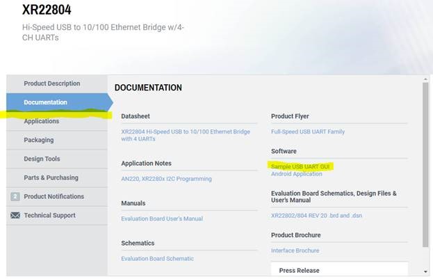
Yes: Go to the product page (XR22804 example below), click on the documentation tab on left, click on “Sample USB UART GUI” under Software:
All of MaxLinear / Exar's USB UARTs are CDC class / CDC-ACM compliant, except for XR21B1421 which is an HID class device. This means they can use a native CDC driver. All major OS have native CDC drivers, except Windows prior to Windows 10.
None of the MaxLinear / Exar USB UARTs require their custom driver, however they will have certain limitations when not using it. The native CDC driver is not capable of accessing the internal memory map of any device. As a result, when using the native CDC driver, the device “defaults” to a particular configuration. The main implications of this default configuration are that hardware RTS/CTS flow control is enabled and that other settings / advance settings are not configurable. Some devices, for example the XR21B1411 which has an internal OTP memory, can be programmed to change this default configuration, but the configuration cannot be changed “on the fly”.
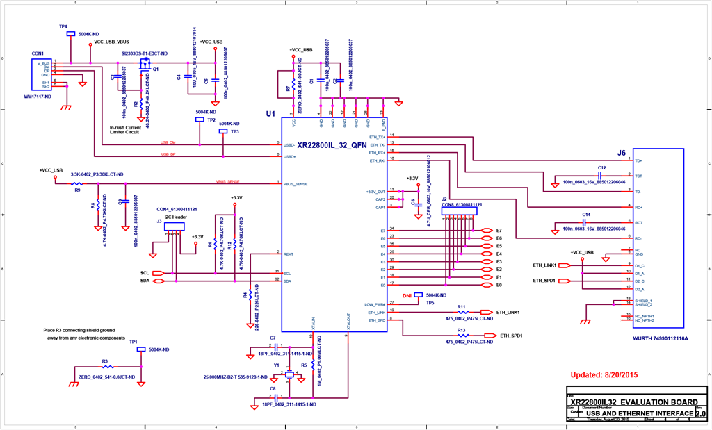
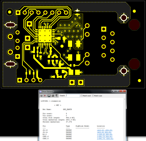
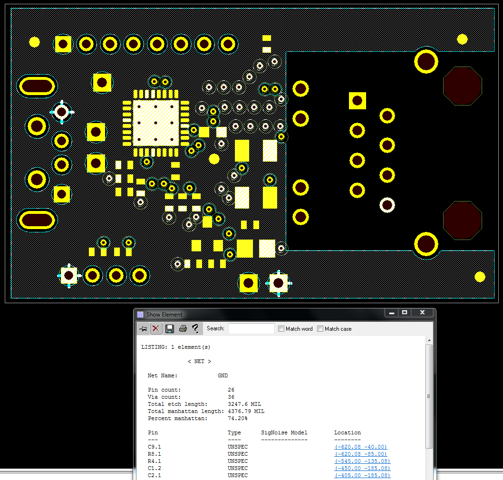
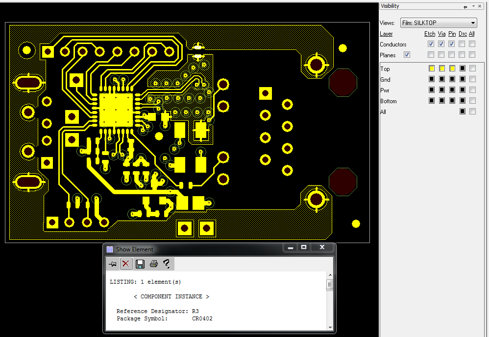
For thermal and ESD benefits, the following PCB design is recommended to provide thermal and electrostatic paths:
1. Design the PCB to conduct heat away from the device using thermal vias under the QFN IC to the digital ground plane.
2. Mount the metal shells of the USB and Ethernet connectors to a separate Chassis / Earth ground.
3. Place the chassis / earth ground metal on one PCB layer, digital ground on another PCB layer and connect through a zero ohm resistor located away from sensitive electronic devices as much as possible.
4. Place a large metal trace for the Earth ground all the way surrounding the PCB, except under the Ethernet connector.
As an example, see the schematic and an example PCB layout for the XR22800 Evaluation Board below: