Overview
| Information | High Performance Quad PCI Express UART |
|---|---|
| Data Bus Interface | PCIe 2.0 (2.5Gbps) |
| # of Channels | 4 |
| Max Data Rate (Mbps) | 31.25 |
| Tx/Rx FIFO (Bytes) | 256/256 |
| FIFO Level Counters | ✔ |
| Program. Trigger Levels | ✔ |
| Auto Flow Control | ✔ |
| Auto RS-485 Half-Duplex Control | ✔ |
| Multidrop (9-bit) Mode | ✔ |
| Fractional Baud Rate Generator | ✔ |
| Power Down Mode | ✔ |
| 5V Tolerant Inputs | |
| IrDA Sup | ✔ |
| Supply Voltage Range VCC (V) | 3 to 3.6 |
| No. of GPIOs | 16 |
| Max UART/GPIO Input Voltage (V) | VCC |
| Max UART/GPIO Output Voltage (V) | VCC |
| Temperature Range (°C) | -40 to 85 |
| Package | FPBGA-176 |
The XR17V354¹ ((V354) is a single chip 4-channel PCI Express (PCIe) UART (Universal Asynchronous Receiver and Transmitter), optimized for higher performance and lower power. The V354 serves as a single lane PCIe bridge to 4 independent enhanced 16550 compatible UARTs. The V354 is compliant to PCIe 2.0 Gen 1 (2.5GT/s).
In addition to the UART channels, the V354 has 16 multi-purpose I/Os (MPIOs), a 16-bit general purpose counter/timer and a global interrupt status register to optimize interrupt servicing.
Each UART of the V354 has many enhanced features such as the 256-bytes TX and RX FIFOs, programmable Fractional Baud Rate Generator, Automatic Hardware or Software Flow Control, Auto RS-485 Half-Duplex Direction Control, programmable TX and RX FIFO Trigger Levels, TX and RX FIFO Level Counters, infrared mode, and data rates up to 31.25Mbps. The V354 is available in a 176-pin fpBGA package (13 x 13 mm).
NOTE¹: Covered by U.S. Patents #5,649,122, #6,754,839, #6,865,626 and #6,947,999
- Single 3.3V power supply
- Internal buck regulator for 1.2V core
- PCIe 2.0 Gen 1 compliant
- x1 Link, dual simplex, 25Gbps in each direction
- Expansion bus interface
- EEPROM interface for configuration
- Data read/write burst operation
- Global interrupt status register for all four UARTs
- Up to 31.25 Mbps serial data rate
- 16 multi-purpose inputs/outputs (MPIOs)
- 16-bit general purpose timer/counter
- Sleep mode with wake-up Indicator
- Four independent UART channels controlled with
- 16550 compatible register Set
- 256-byte TX and RX FIFOs
- Programmable TX and RX Trigger Levels
- TX/RX FIFO Level Counters
- Fractional baud rate generator
- Automatic RTS/CTS or DTR/DSR hardware flow control with programmable hysteresis
- Automatic Xon/Xoff software flow control
- RS-485 half duplex direction control output with programmable turn-around delay
- Multi-drop with Auto Address Detection
- Infrared (IrDA 11) data encoder/decoder
- Software compatible to XR17C15x, XR17D15x, XR17V25x PCI UARTs
- Download Software Drivers
- Next generation Point-of-Sale Systems
- Remote Access Servers
- Storage Network Management
- Factory Automation and Process Control
- Multi-port RS-232/RS-422/RS-485 Cards
Documentation & Design Tools
| Type | Title | Version | Date | File Size |
|---|---|---|---|---|
| Data Sheets | XR17V354 High Performance Quad PCI-Express UART | 1.0.5 | August 2018 | 3.8 MB |
| Application Notes | DAN-190, MaxLinear UARTs in RS-485 Applications | R01 | July 2023 | 2.4 MB |
| Application Notes | AN-225, Installing and Testing a PCI/PCIe UART Serial Port Using a Custom MaxLinear Driver in Linux | 1B | July 2018 | 427.1 KB |
| Application Notes | AN 209 - Windows & Linux API interface code for PCI/PCIe UARTs’ drivers | December 2011 | 199.5 KB | |
| Application Notes | AN-204, UART Sleep Mode | 1.0.0 | June 2010 | 515.8 KB |
| Application Notes | AN-206, EEPROM Programming for PCIe UARTs | 1.0.0 | June 2010 | 183.2 KB |
| User Guides & Manuals | XR17V35x MPIO Tool User Manual | R00 | March 2024 | 3.3 MB |
| User Guides & Manuals | XR17V35x PCIe UARTs Design Guide | 00 | April 2020 | 2.3 MB |
| User Guides & Manuals | XR17V358/354 Evaluation Board User's Manual | R00 | November 2018 | 19.9 MB |
| User Guides & Manuals | PCI/PCIe EEPROM Programming Utility User Manual | 1.0.0 | November 2010 | 262.5 KB |
| Software: GUIs & Utilities | XR17V35x MPIO Test Tool | 1.0.0.0 | March 2024 | 1.4 MB |
| Software: GUIs & Utilities | PCIe "Super GUI" | 1009 | September 2018 | 1.8 MB |
| Software: GUIs & Utilities | XR17V35x Windows EEPROM Programming Utility | 1.0 | July 2017 | 1.7 MB |
| Software: GUIs & Utilities | XR17V35x Linux EEPROM Programming Utility | 1.0.0 | April 2013 | 161.7 KB |
| Errata | XR17V35X Errata | R01 | July 2022 | 2.3 MB |
| Product Flyers | High Performance Dual/Quad/Octal PCI Express UARTs | November 2009 | 257.7 KB | |
| Whitepapers | Enhancing Connectivity with MaxLinear XR21xxx USB-UART Bridges | R00 | September 2025 | 808.2 KB |
| Software: Drivers | Windows 10 | 5.5.0.0 | September 2020 | 319.1 KB |
| Software: Drivers | Linux 2.6.32 and newer | 2.6.0.0 | August 2019 | 20.2 KB |
| Software: Drivers | Windows XP, Vista, 7, 8, 8.1 | 5.3.0.0 | September 2015 | 275.2 KB |
| Software: Drivers | Linux 2.6.16 | 1.0.0 | April 2010 | 13.3 KB |
| Software: Drivers | Linux 2.6.31 | 1.0.0 | February 2010 | 12.7 KB |
| Software: Drivers | Linux 2.6.27 | 1.0.0 | November 2009 | 12.7 KB |
| Schematics & Design Files | XR17V358IB/SP339 E8 Evaluation Board BRD, RSN Files | REV 40 | June 2016 | 1.6 MB |
| Schematics & Design Files | Schematic | 4.0 | January 2016 | 296.6 KB |
| Product Brochures | Serial Transceivers & Bridges Brochure | R03 | May 2025 | 3.6 MB |
Quality & RoHS
Parts & Purchasing
| Part Number | Pkg Code | Min Temp | Max Temp | Status | Buy Now | Order Samples |
|---|---|---|---|---|---|---|
| XR17V354IB176-F | L-fpBGA176 | -40 | 85 | Active | Order | |
| XR17V354/SP339-0A-EB | Board | Active | ||||
| XR17V354/SP339-E4-EB | Board | Active | ||||
| XR17V354/SP339-E8-EB | Board | Active |
Active - the part is released for sale, standard product.
EOL (End of Life) - the part is no longer being manufactured, there may or may not be inventory still in stock.
CF (Contact Factory) - the part is still active but customers should check with the factory for availability. Longer lead-times may apply.
PRE (Pre-introduction) - the part has not been introduced or the part number is an early version available for sample only.
OBS (Obsolete) - the part is no longer being manufactured and may not be ordered.
NRND (Not Recommended for New Designs) - the part is not recommended for new designs.
Packaging
| Pkg Code | Details | Quantities | Dimensions |
|---|---|---|---|
| L-fpBGA176 |
|
|
|
Notifications
FAQs & Support
Search our list of FAQs for answers to common technical questions.
For material content, environmental, quality and reliability questions review the Quality tab or visit our Quality page.
For ordering information and general customer service visit our Contact Us page.
Submit a Technical Support Question As a New Question
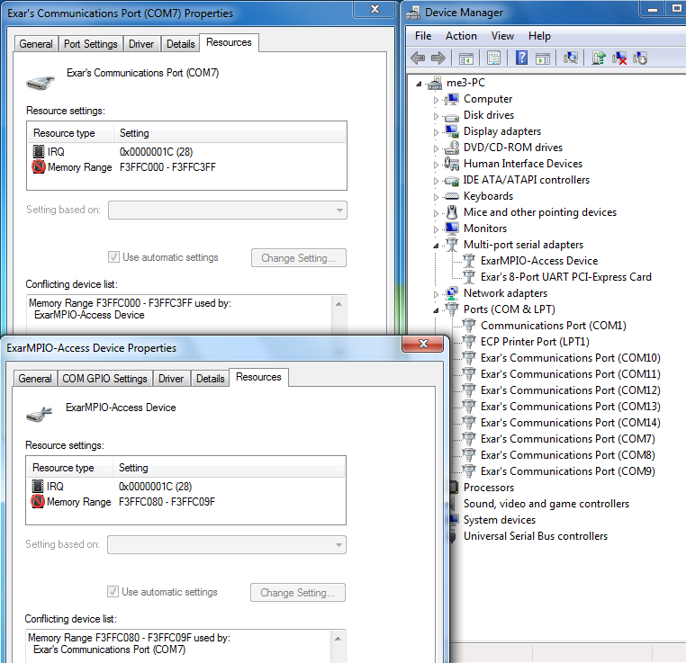
For some UARTs, Microsoft certified drivers are available for Windows Operating System and can be downloaded via Windows Update. These drivers and others, including for Linux and other Operating Systems can be found by visiting https://www.exar.com/design-tools/software-drivers Please note Software Driver Use Terms.


Click on the version link under Driver Version of the desired type of UART, part number and operating system. A zip file is downloaded which contains a ReadMe file with instructions.
Links to datasheets and product family pages are in the software driver table for easy reference.The XR17Cxxx, XR17Dxxx, and XR17Vxxx are all UARTs but have the following basic differences:
- PCI UARTs
- XR17Cxxx – 5V supply, up to 33MHz clock input
- XR17Dxxx – 5V or 3.3V supply, up to 33MHz clock input
- XR17V2xx – 3.3V supply, up to 66MHz clock input
- PCIe UARTs
- XR17V3xx – 3.3V supply, up to 125MHz clock input
Find the product page of the part that you want to get an evaluation board for and click on Parts & Purchasing. Example:

Click on Parts & Purchasing or Order Now. Locate the icons under Buy Now or Order Samples:

Click on the Buy Now icon and see who has stock and click on the Buy button:

Alternatively, you can click on the Order Samples icon to request a sample.
Note, not all products are sampleable from the website.

If the icons are missing, create a support ticket.
https://www.exar.com/quality-assurance-and-reliability/lead-free-program
Visit the product page for the part you are interested in. The part's status is listed in the Parts & Purchasing section. You can also view Product Lifecycle and Obsolescence Information including PDNs (Product Discontinuation Notifications).
To visit a product page, type the part into the search window on the top of the MaxLinear website.
In this example, we searched for XR33180. Visit the product page by clicking the part number or visit the orderable parts list by clicking "Orderable Parts".

The Parts & Purchasing section of the product page shows the Status of all orderable part numbers for that product. Click Show obsolete parts, to see all EOL or OBS products.

The instructions for adding the Multi-function Driver are described by Microsoft:
https://msdn.microsoft.com/en-US/library/ff794057(v=winembedded.60).aspx
1. Native drivers: Native drivers may be found in all major OS such as Windows, Linux, and Max OSX. Typically these drivers will be automatically loaded. In some cases, these are basic drivers and may have limitations on advanced device functionality, however. USB HID, Hub and CDC-ACM drivers are examples of native drivers. The CDC-ACM driver be used with our CDC-ACM class USB UARTs, but has limited functionality.
2. MaxLinear custom drivers: MaxLinear custom drivers may be used to support additional functionality in MaxLinear devices. For example, the MaxLinear custom driver for USB UARTs overcomes the limitations of the native CDC-ACM driver. See https://www.exar.com/design-tools/software-drivers for a list of and access to the drivers that we currently have. In some cases, the MaxLinear driver can also be customized, or source code can be provided after executing a Software License Agreement.
Please check that all the following conditions are satisfied first.
- no interrupts pending (ISR bit-0 = 1)
- modem inputs are not toggling (MSR bits 0-3 = 0)
- RX input pin is idling HIGH • divisor (the value in DLL register) is non-zero
- TX and RX FIFOs are empty
Be sure sleep mode bit has been set to 1. If there are multiple UART channels, the sleep conditions must be true for all channels.
See more on Sleep Mode in AN204 UART Sleep Mode.
Yes. Note: some devices do have powersave mode. If UART goes into powersave mode, then the registers are not accessible.
See more on Sleep Mode in AN204 UART Sleep Mode.
Read LSR register to check whether the UART receives the data or not.
- If LSR value is 0x60, it means that either UART receiver FIFO doesn’t receive the data or the data in receiver FIFO has been read out before the read of LSR.
- If LSR value is 0x00, it means data is still in the THR (clock doesn’t oscillate to transmit data).
- If LSR value is 0xFF, it means either UART is in powersave mode or UART is powered off. For those devices with powersave mode, be sure that UARTS are not in powersave mode.
See more on Sleep Mode in AN204 UART Sleep Mode.
Videos
MxL UARTs Auto RS-485 Direction Control
This video describes how the automatic RS-485 half-duplex direction control feature in MaxLinear UARTs reduces driver development and frees up CPU/MCU loading. This feature eliminates the need to monitor the status of the UART’s transmit shift register and automatically switches MaxLinear RS-485 transceivers from the transmit mode to the receive mode. This video summarizes the content in application note DAN-190.